Thursday, November 11, 2021

Bugs in Complex Software

In the picture: history's first bug.

Complex software will be guaranteed to have bugs in it. And most of the bugs are caused by state changes.

The human mind has limited capacity of keeping track of state (data, variables.) Hence, there is a discrepancy between what the state looks like in the programmer's mind, and what it actually looks like.

How does state change?

Where in the code does the state change?

When does the state change?

In what order does the state change?

And even... why doest the state change?

The mental picture of those, formed by the programmer, is very poor.

So.. bugs!

There is of course a paradigm where state-change plays a zero roll: functional programming. But despite decades of trying, we have not been able to practically use that in complex software. Mainly because the real world deals with state. Try making a video game that carries no state!

John Carmack once did an impromptu talk on functional programming and video games, and made in interesting observation that you could write an AI/sim that takes the entire world as function input, and produces the entire world as its output.

About John's example of a one-person hallway... I think the solution is simple. Input for hall-entering needs more than the current entity. It needs a list of all other entities that want to enter. Then use a heuristic to choose which one can actually enter. Done.

So yeah... complex state changes. As long as we have not harnessed the complexity of state, I find it pretty futile to crusade against C's unsafe memory referencing, e.g. A bug caused by following a dangling pointer is so shallow, compared to a bug caused by asynchronous state changes racing to completion. Throw in multiple threads, multi-player, and it will be too hard to reason about.

Sunday, November 7, 2021

Switching

I've been learning a lot about transistors, lately. This is because I found myself having to switch a load that would be too large for an IO pin. Here I summerize my newly gathered knowledge on them.

A BJT transistor is switched ON/OFF using current at the base. This current is then multiplied at Collector/Emitter.

To tune the current flowing through the base, we need a bias resistor. This makes PCB design bulkier, but you can get pre-biased transistors. I find I need to get them with a low Ohm bias, else my transistor will not switch fully on.

BJT comes in two variants, NPN and PNP. The schematic symbol differs in which way the arrow points. Mnemonic: NPN has the arrow "Not Pointing iN."

PNP transistors can be used to switch a load at its high-side: You cut the load's connection to V+ ON/OFF.

NPN transistors can be used to switch a load at its low-side: You cut the load's connection to GND ON/OFF.

MOSFET transistors are often a better choice, unlike of BJT's current based switching, the switch based on voltage at the gate.

MOSFET comes in two variants, P-CHANNEL and N-CHANNEL.

P-CHANNEL transistors can be used to switch a load at its high-side: You cut the load's connection to V+ ON/OFF. A 0V at the gate will switch on the transistor. Source is connected to V+ and Drain is connected to the load.

N-CHANNEL transistors can be used to switch a load at its low-side: You cut the load's connection to GND ON/OFF. A V+ at the gate will switch on the transistor. Source is connected to GROUND and Drain is connected to the load.

To simplify a PCB design, you can get two transistors that share its housing in an "Array."

Wednesday, October 27, 2021

Bi-Colour LED bars.

I am evaluating bi-colour LEDs that are RED/GRN, and can be mixed to ORANGE/YELLOW. The two candidates are SunLED GMDKVGX10D and KingBright DC10EGWA.

I've found that the SunLED has a bright GREEN with an even brighter RED. You need to drive the green channel with at least double the current of the red, to match them. I find that 1kΩ and 2kΩ work for my application.

The KingBright, on the other hand, doesn't show much difference between the RED and GRN brightness. But both are far less bright than the SunLED. Even though the KingBright has the term "High Efficiency" in the data sheet? When I limit both RED and GRN with 470Ω I find it is still quite a bit dimmer than the SunLED at 1kΩ/2kΩ.

What both models do the same: they have the GRN/RED LEDs share their cathode, not their anode. A common-anode design would have been so much more convenient. You would have been able to drive it with a constant current LED driver that is a current sink. All constant current LED drivers that I could find are current sinks, so none of them can be used with these LEDs. So not Texas Instruments TLC591x, nor TLC592x and neither a Maxim6966 would work. I consider this a strange design decision.

Another feature I miss, is an 8-segment version of these bar-graphs. It's just more convenient to work with 8-bit quantities. Or in the case of bi-colour bar-graphs: 16-bit would be preferable over 10-segment 20-bit units. Monochromatic, and fixed-colour bar-graphs come in more varied sizes, like 8-segment, 10-segment and even 12-segments sometimes.

Thursday, October 21, 2021

Transistor

I am using the TLC5928 constant current sink driver to light up my LED bar graphs.

The neat thing about this part, is that you can set a current (for all 16 outputs) using a reference resistor. The higher the resistor, the less current the chip will output. So far so good.

If you have a LED bar graph that has both GRN and RED LEDs in it, you have a problem, though. The RED is a lot brighter, and does not need nearly as much current as the GRN one. I see typically a factor 4x more current for green. However, the reference resistor sets the current for ALL channels, whether they have a red or a green LED on it.

So, how to proceed? Well, I decided to do add pulse-width-modulation for the red LEDs. I will still drive all channels with the same constant current, but the red LEDs will have their anode voltage (3.3V) interrupted at a few hundred hertz, with a specify duty-cycle. Whereas the green leds will keep seeing their uninterrupted voltage.

A GPIO pin can never deliver the current required to switch a whole bunch of red LEDs. So we introduce a little switch, called a Bipolar Junction Transistor of the PNP form.

When adding a discrete transistor to do perform this PWM job, I also need to add resistors, which makes the design more cluttered. Fortunately, you can buy pre-biased transistors that already house those resistors along with the transistor. I have evaluated 3 such pre-biased transistors for this job.

DTB114EK (R1 and R2 are 10kΩ)

DTB123TK (R1 is 2.2kΩ)

DTB113ZC (R1 is 1kΩ and R2 is 10kΩ)

Note that in my case, I have 3.3V at the emitter (pin1) and not GND.

I've found that a high R1 resistor at the base of the transistor causes the EMITTER->COLLECTOR current to be too limited when the transistor is switched on. Even when I have a continuous '0' at the base, to switch it on, the current does not get high enough to drive many LEDs. Hence, between these three, the DTB113ZC with a 1kΩ resistor at the base does the best job for my application. I find that if I have a bunch of LEDs drawing 109mA in total, and switch that current with the transistor, 90mA makes it through with the DTB113ZC, 79mA makes it through with the DTB123TK and 47mA makes it though with the DTB114EK.

Tuesday, October 19, 2021

The state of Electronic Circuit Simulation Software under Ubuntu.

Today, I was in need of electronic circuit simulation. Let's see what is available for Ubuntu.

First I tried ngspice, but that seems to be text based.

$ ngspice 
******
** ngspice-34 : Circuit level simulation program
** The U. C. Berkeley CAD Group
** Copyright 1985-1994, Regents of the University of California.
** Copyright 2001-2020, The ngspice team.
** Please get your ngspice manual from http://ngspice.sourceforge.net/docs.html
** Please file your bug-reports at http://ngspice.sourceforge.net/bugrep.html
** Creation Date: Sat Mar  6 03:53:35 UTC 2021
******
ngspice 1 ->

Ok, install the GUI for it then...

$ sudo apt install gspiceui
Reading package lists... Done
Building dependency tree... Done
Reading state information... Done
Package gspiceui is not available, but is referred to by another package.
This may mean that the package is missing, has been obsoleted, or
is only available from another source

Next up: Oregano. I managed to compose a circuit, but when I tried to simulate:

$ oregano 
XXXXXXXXXXXXXXXX
XXXXXXXXXXXXXXXX 0x555ee9aeaf10 FALSE
Segmentation fault

Next up: xschem. Again, I managed to draw a schematic, which is done in an awkward way. When I wanted to simulate, I could find no such option in the menus. It seems it cannot?

Ok, let's move to QUCS. No hit on a package search in Ubuntu, which does not bode well. Ok, let's grab a deb from the archive.

# dpkg -i qucs_0.0.20.201022-2_amd64.deb 
Selecting previously unselected package qucs.
(Reading database ... 281811 files and directories currently installed.)
Preparing to unpack qucs_0.0.20.201022-2_amd64.deb ...
Unpacking qucs (0.0.20.201022-2) ...
dpkg: dependency problems prevent configuration of qucs:
 qucs depends on libqt4-qt3support (>= 4:4.5.3); however:
  Package libqt4-qt3support is not installed.
 qucs depends on libqt4-script (>= 4:4.5.3); however:
  Package libqt4-script is not installed.
 qucs depends on libqt4-svg (>= 4:4.5.3); however:
  Package libqt4-svg is not installed.
 qucs depends on libqtcore4 (>= 4:4.7.0~beta1); however:
  Package libqtcore4 is not installed.
 qucs depends on libqtgui4 (>= 4:4.8.0); however:
  Package libqtgui4 is not installed.

dpkg: error processing package qucs (--install):
 dependency problems - leaving unconfigured
Processing triggers for libc-bin (2.33-0ubuntu5) ...
Processing triggers for desktop-file-utils (0.26-1ubuntu1) ...
Processing triggers for mailcap (3.68ubuntu1) ...
Processing triggers for gnome-menus (3.36.0-1ubuntu1) ...
Processing triggers for hicolor-icon-theme (0.17-2) ...
Processing triggers for man-db (2.9.4-2) ...
Processing triggers for menu (2.1.47ubuntu4) ...
Errors were encountered while processing:
 qucs
root@Workstation:/home/bram/Downloads# apt install libqt4-script libqt4-svg libqtcore4 libqtgui4
Reading package lists... Done
Building dependency tree... Done
Reading state information... Done
Package libqtcore4 is not available, but is referred to by another package.
This may mean that the package is missing, has been obsoleted, or
is only available from another source

Maybe GEDA?

# apt install geda
Reading package lists... Done
Building dependency tree... Done
Reading state information... Done
Package geda is not available, but is referred to by another package.
This may mean that the package is missing, has been obsoleted, or
is only available from another source

E: Package 'geda' has no installation candidate

Oh dear... I am about to give up now. I can see now, why CircuitLab manages to charge $399,- per year.

Friday, October 8, 2021

The SMD Hurdle

I found that programming microcontrollers and designing electronic circuits is so much more fun than modern software development for PC. I have really taken to the hobby. So much so, that I'm beginning to think a pivot is in order.

When I started mobile game development in feb 2009, I was ahead of the curve. So far ahead of the curve, that app-store money was easy to come by. No game engines, no unity available. Everything had to be custom roll-your-own code. The number of people that knew OpenGL and ObjectiveC was near zero. It was good to be at the start-point of the democratization of software development. Fast forward to today, and the market is so crowded, it is impossible to stand out.

Just as the iPhone opened up a cottage industry of app developers, I think there is a new wave that you can ride, that is not very crowded. Chinese PCB factories have made electronics design accessible to all. For $40 dollars or so, you can have your PCB printed manufactured in a small batch. And if you add a few hundred, you can even get the procurement, and placement of the components on your board, for full service fabrication of your design. Not bad!

Hence, the last few weeks, I have been designing electronic circuits using EasyEDA. It's an easy to use, free PCB design tool. I like it a lot, except for the slow cloud operations that it relies on for many of its operations. But kudos to them for providing a Linux client for it.

So far, I have ordered PCB service from both JLCPCB and PCBWay. Those are the two biggest players in the PCB market, both located in China. From JLCPCB I ordered my first design, which was Through-Hole components only, so I could do the assembly myself. From PCBWay I ordered full service PCB with assembly and component procurement included. That was quite a bit more expensive. And that order has not been completed yet, as it still waits for component delivery. The JLCPCB order did arrive already, and is shown below.

I'll go into the actual product that I am designing, at a later time. But currently, the design is getting more and more complex. The second version had SMD components, so I had pcbway do that for me.

Revision 3 had even more and even smaller components, in a QFN-24 (0.5mm spacing) package even! And to make matters worse: at both sides of the PCB. This is because my design is densily integrated and has space constraints, so I needed both sides of the board. As I was preparing my order for assembly at JLCPCB, the site told me that two-sided SMD assembly was not supported. I had to pick one side, which they would do for me. Ugh.

So, I need to reexamine my options. Would SMD mounting be something I could attempt myself? I've always backed away from it, as being too much of a hurdle.

But some makers with SMD DIY videos have convinced me that it must be possible. So I decided to have a go at it, myself! Surface mounting tiny little components on a PCB.

For this, I will be ordering a set of new tools:

  • A re-work station, which is just a temperature controlled heat-gun.
  • Solder paste (a mix of metal, solder, flux.)
  • Scraper.
  • Tweezers.
  • Big-ass magnifying glass.

In addition of all this, I must make sure that I order my PCBs with a stencil plate. This stencil will help me apply the paste to where it is needed.

In a good fortune of events, the manufacturer of the leading soldering paste is from Canada. Nice! No import duties, and fast shipping.

Anyways, wish me luck!

Oh no! That is too small!

Tuesday, September 21, 2021

LED Bars

Two LED bar graphs. You would think they would be much alike, but no.

On the left: LTA-1000Y (2017 Thailand.) On the right: FJB10Y.

The polarity is reversed. The LTA has anode on the side of the first pin. The FBJ has the cathode on the side of the first pin.

The obvious difference: face colour grey vs face colour black.

Light colour is similar, but brightness is much different. I need to use 470 ohm resistor with the LTA, and a 2K ohm resister with the FJB.

I did some extra research on another convention, for multi-coloured bars. Is RED on top or on the bottom of the bar?:

  • AVAGO HDSP-4832 has R/R/R/Y/Y/Y/Y/G/G/G with pin 1 as RED anode.
  • KingBright DC7G3HWA has G/G/G/G/G/G/G/R/R/R with pin 1 as GRN anode.
  • Fairchild MV5A164 (obsolete) has R/R/R/Y/Y/Y/Y/G/G/G with pin 1 as RED anode.
  • Fairchild MV5C164 (obsolete) has G/G/G/G/G/G/Y/Y/Y/R with pin 1 as GRN anode.
  • KYX B10BBGYR has B/G/G/G/G/Y/Y/Y/R/R with pin 1 as BLU anode.
  • MT1025CTF has G/G/G/G/G/Y/Y/Y/R/R with pin 1 as GRN anode. Pin 1 (unmarked) at side that has print.
  • SunLED XGMDKVGX10D has 10+10 bi-colour LEDs to interpolate between GRN to YLW to RED. To use them, 2k Ohm on R and 470 Ohm on G works well. Unfortunately, it is a common-cathode setup, which makes it useless for standard LED drivers.
  • F2510GHR has G/G/G/G/Y/Y/Y/Y/R/R with pin 1 as GRN cathode. It is easy to connect incorrectly. UNLIKE ALL OTHERS, THIS ONE HAS PRODUCT NUMBER PRINTED AT CATHODE SIDE (BUT STILL AT PIN1 SIDE.) Gorgeous colours though, with the yellow being more like amber, A nice looking green that is not very bright, though.
  • F2510HYG has R/R/R/R/Y/Y/Y/G/G/G with pin 1 as RED anode.

Some 8 segment led bars:

  • F2010RG is R/R/G/G/G/G/G/G with pin1 as red anode.
  • KYX-B08GOR is G/G/G/G/G/G/R/R with pin1 as grn anode.

Monday, September 20, 2021

Arduino

Last year, I did a project with the Arduino Micro kit. This is an ATmega32U4 microcontroller.

With it, I built a USB input device, with knobs, to tune my noise fields for Ring Miner.

In that project, I was simultaneously writing USB HID data, reading turn knobs, and writing OLED displays. In order to avoid stalls I had to modify the standard lib so I could skip writing USB data if there was no space available in the buffer, which is what happens when the PC is not reading the USB HID device.

I have recently picked up the Arduino again. This time to see if I can steer LED bar graphs with it. I noticed that out of the box, Ubuntu's arduino IDE will not run. You need to patch a library before it will run.

I have been learning on how to drive LEDs with a constant current shift register. I think I will end up using the TLC5917IN chip. Unfortunately, it is only 8 bit, I would have preferred 10 bits, but it was available in-stock, and affordable.

The simplicity of micro controllers is refreshing, in this age of super complexity. Close to the metal, and straightforward.

When coding for micro controllers, use static PROGMEM const qualifier for your data that you want to reside in ROM, instead of RAM.

Sunday, July 4, 2021

Catching a fall (procedurally.)

I have been doing a lot of procedural animation, lately. Making a humanoid walk, and swing a torch at spiders.

I also needed a proper way to catch a fall, with the legs. Because I already had the Inverse Kinematics sorted, I just needed to shift the pelvis down, and up, after a fall.

To do this convincingly, I need to drop down hard at the start, then ease at the nadir, and ease again on the way back to the zenith. For this, piecewise functions come to the rescue. I ended up using this:

Monday, June 21, 2021

Field Of View

Computer monitors come in different aspect ratios. From the old school 4:3 to the ridiculous 32:9.

In my 3D games, I have to choose a Field-Of-View for the camera. Wide angle, or narrow angle views? To do this, the convention is to set a fixed vertical field of view, and then adopt the horizontal field of view that falls out of it, based on the image aspect ratio. I use this for all my 3D games: set the vertical F.o.V.

Fixing the Vertical Field of View, means that users on 4:3 monitors see less of the world, and users on ultra wide screen see more of the world. This could pose an unfair advantage.

An additional problem is that ultra wide aspect ratios lead to ultra wide angle views, which lead to a lot of distorted shapes in the corners of the screen.

But fixing the Horizontal Field of View instead, would mean that users on wide-screen would see less of the world (at top and bottom parts of screen.) This made me wonder... what if I were to fix the angle for the diagonal field instead? Fixed for all users. And then let the Horizontal/Vertical angles fall out of this.

Definitely worth an experiment! So let's do some trigonometry!

Problem: given a fixed angle for the diagonal field of view... what are the corresponding Vertical and Horizontal fields of view?

Given the fixed diagonal field of view angle α, and a given image height h, and image diagonal d, we need merely two equations to derive the vertical field of view angle β.

And with that angle β we can set up our projection matrix the usual way.

When we do all this, we go from extremist views (with fixed vertical FoV) like these:

...to more moderate views (with fixed diagonal FoV) like the ones below. Note that the view angles change less than in the case above, between aspect ratios. The narrow aspect ratio does not show that much less on left/right, and for what it loses on the sides, it wins a little on top/bottom. I think this approach is a keeper!

For completeness, the code, which is trivial:
float vertical_fov_from_diagonal_fov( float a, float w, float h )
{
        const float d = sqrtf(w*w + h*h);
        const float m = d / ( 2 * tanf( a / 2 ) );

        const float b = 2 * atanf( h / (2*m) );
        return b;
}
  

Monday, June 14, 2021

Fire in OpenGL

(Just 120 particles, looks better in 60Hz and without GIF artifacts.)

This is a quick 'n dirty approach for getting a fire visualization using OpenGL.

Fire blends somewhat with its background, so we will be using blending. But unlike regular transparency, fire works a little different: it only adds light to your framebuffer, never removes it. For this, the blendmode GL_ONE, GL_ONE is perfect!

Ok, now we know how to draw it, which leads to the question, on what to draw. I find that the majority of approaches you find on the web go for textured billboard. But I think that it is better to go with geometry instead, that is un-textured. By adding some shape to the geometry that you draw, you can save on the number of particles you need to draw. I opted for a spikey kind of vortex, as shown below.

From the picture above you can see there is already an inherent counter-clockwise rotation in the model, which we should replicate in the animation. So as we draw each particle, we should keep rotating the billboard we draw for it. Of course, the billboard needs to be oriented to the camera as well! Which means we have to do a little math in the vertex shader.

#version 150

in mediump vec4 position;	// per vert: vertex position.

in mediump vec4 bdpos;		// per inst: bill board pos.
in mediump vec4 rgb;		// per inst: colour.
in mediump float scale;		// per inst: scale.
in mediump float angle;		// per inst: angle.

out lowp vec3 colour;		// to fragment shader: colour.

uniform highp mat4 modelcamviewprojmat;
uniform highp mat4 camtrf;

void main()
{
	vec4 camx   = camtrf[0];
	vec4 campos = camtrf[3];
	highp vec4 scaledpos;
	scaledpos.xyz = position.xyz * scale;
	scaledpos.w = 1.0;
	vec3 z = bdpos.xyz - campos.xyz;
	z = normalize(z);
	vec3 camy = camtrf[1].xyz;
	vec3 xx = cross( camy, z );
	vec3 yy = cross( xx, z );
	vec3 x = xx *  cos(angle) + yy * sin(angle);
	vec3 y = xx * -sin(angle) + yy * cos(angle);
	mat4 trf = mat4(1.0);
	trf[0].xyz = x;
	trf[1].xyz = y;
	trf[2].xyz = z;
	trf[3] = bdpos;
	highp vec4 tpos = trf * scaledpos;
	colour = rgb.rgb;
	gl_Position  = modelcamviewprojmat * tpos;
}
  

Let us break down that vertex shader. Like any vertex shader for 3D graphics, it transforms a vertex (position) using a modelviewprojection matrix, no surprised there.

All the other inputs for this shader are per-instance attributes, not per-vertex attributes. So you need to call glVertexAttribDivisor() for them, with value 1.

Every particle billboard has a position (bdpos,) a colour (rgb,) a size (scale,) and a rotation (angle.)

The scale we just apply to the model's vertex position before we transform the vertex to clip-space. And the colour is passed onto the fragment shader, as-is.

Note that we don't just pass the modelviewprojection matrix, but also a second matrix: the camera transformation. This is just the view matrix, before it got inverted from camera to view. We need this, so that we can reconstruct a proper orientation for our billboard. We create a model transform for the billboard with Z pointing to our camera. This is basically (xx,yy,z, bdpos). But we skew the xx,yy axes with the particle's rotation angle, so that we end up with the (x,y,z, bdpos) transform. To skew them, the new x,y are both just a linear combination of the old xx,yy with the cos/sin factors.

Once we applied, this per-particle transformation to the (scaled) vertex position, we get our transformed position (tpos.) That, can finally be transformed with the modelviewproj matrix to give us our final result.

That covers the GPU-side of things. But we still need to fill in the proper rgb/scale/angle values on the CPU-side.

The scale is easy: because gas disperses as it burns, we just have to make the particle grow in size, as it ages. The angle is easy too, I just apply a rotational velocity that scales with the linear velocity of the particle, always in the same direction (counter clockwise.)

That leaves us with the colours. We use GL_ONE, GL_ONE, and it is best to use low colour values, so that sharp boundaries between particle and no particle are not too obvious. Also, we should slowly fade-out our particles. So as the particle ages, I make it go fainter! And for the chromatic transitions, just make the particle go from whitish, to yellowish to reddish, and you should be good.

I am using this approach in my project for Real Time Global Illumination, where I use the particles as light sources.

Monday, May 24, 2021

Things that farming Chia will make you aware of.

When you farm Chia, the proof-of-space blockchained coin, you learn a few new things.

  • Which PCIe generation your motherboard offers
  • NVMe performance
  • NVMe endurance
  • The fstrim command
  • XFS options like crc=0
  • What the term JBOD means
  • The performance of NFS over your LAN
  • The thermal characteristics of your drives
  • The difference between peak write bandwidth and sustained write bandwidth
  • The Crucial P1 and PNY XLR8 have incredibly slow write bandwidth. Avoid!

So far, this has been a fully educational excercise, with zero financial pay-off: My 6 drives can't compete with the netspace. But stream-lining your computer for plotting was a fun exercise in optimization.

If nothing else, I at least got a rather popular Open Source Tool out of it, in my portfolio: ChiaHarvestGraph and its sister tools ChiaPlotGraph and ChiaHeightGraph.

Tuesday, May 4, 2021

Directional Light

I have implemented directional light for Practica Boxel. It simulates a harsh distant sun.

Because there is only one bounce, there are fully black shadows with 0% light in the scene. I'm not sure I like it.

It's main advantage is that it is easier to render in chunks, as there is always just one lightsource, which is always the same. No need to cull lightsources, which simplifies things a lot. As local lightsources pop into view, the delta in light is too jarring, so this circumvents that.

I've decided to go back to my original experiments where I have a night-scene with just 1 torch light.

And with one hand-held light source, I find that a first-person camera is a no-go: because if light and camera are close to eachother, the lighting becomes un-interesting, no shadows, not much indirect light, so the whole GLobal Illumination is wasted on it.

Which leaves me with...

A night-time world, one hand-held lightsource (torch) and a third-person camera.

Think: A 3D Ant Attack clone, set at night, and with Global Illumination.

So, when doing a local point-light, I should modify how I shoot my photons again! I started with a cosine weighted hemi-sphere direction. Then I added directional light. And for a torch, I would need a uniform omni-directional light.

So, blue-noise sampling of a sphere it is, then. Alan Wolfe came to the rescue with his suggestion of using Mitchell's Best Candidate algorithm to create progressive blue noise.

As his approach was O(N³) I had to weaken it a bit, but reducing the number of candidates. I implemented it in C, using 16-threads and also 16-wide SIMD for conceptually handling 256 candidates simultaneously. By leaving it running over-night, with my CPU at full blast, I was able to create a data-set of 2M samples that look reasonably like blue-noise.

2 million sample points, viewed from the inside:

So, night-time-Ant-Attack, here I come...

Monday, April 12, 2021

Partwise approach to Global Illumination?

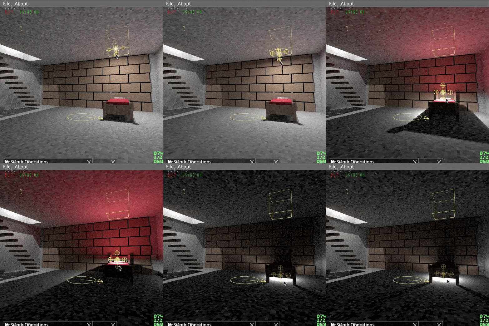
With the implementation of Practica Boxel I was able to verify that for simple (aab primitives) and small (200 blocks) scenes, you can compute indirect light at 60Hz. This is an encouraging result! (Notice the red glow in the room, as the light drops.)

But it does leave me wanting for more... how can I do large scenes? With conventional, direct illumination rendering, you always have the option to split up your world in chunks, and treat them separately. Could I do something similar for Practica Boxel? What if I create a 3x3 grid around my avatar, and only compute indirect light every frame for the center sector? And compute the indirect light of distant sectors sparingly?

And there we hit the first snag: just because a chunk is remote, does not mean it cannot influence indirect light of the center sector. At the very least, we need to consider remote light sources too. If a lightsource is considered at one chunk but not at the next, a division will clearly show up.

Ok, the good news is that with the Photon Mapping approach I use, the use of many lightsources is very cheap. I even added a mechanism to prioritize lightsources, so that more photons are shot from nearby ones.

But there is more to it. Distant geometry also influences the light, either as an occluder of light, or a reflector of light And especially in my implementation, the cost of extra geometry is large! I opted for a linear algorithm that tests all geometry against a photon's path. This eliminates the dynamic branching that a spatial subdivision algorithm would bring, so the CUDA code can blast through it at full speed. This is great for small scenes, not so great for large scenes.

Geometry just beyond a sector's reach will fail to exert its influence on the lighting of objects nearby. I was half-way hoping that the error would be small enough... light falls off with the square of the distance, so should quickly go to zero. In practice, the human eye is just too sensitive to small discontinuities in light.

Six chairs. Spot the sector boundary! Only half of them receive light from the wall.

I guess one way around this, is to have two separate boundaries: the sector boundary itself, and a larger boundary that contains the geometry of influence. But no matter how you set the second one, there will be a distance that separates the inclusion and exclusion of an object, and it will show up.

The other approach would be to suck it up, and abandon real-time calculation of indirect light. Just photon-map the entire world as a whole. And no longer do immediate light calculation. The light would be static, or updated at 1Hz instead of 60Hz. But if it is static, why bother with all this, and not just use Blender or Maya to bake light maps?

Real Time Global Illumination seems so close, but... not quite in reach for complex scenes. To be continued.

Friday, February 12, 2021

On the allocation of photon-budgets for light sources.

I am making a real-time Photon Mapper, called Practica Boxel.

Photon Mapping is an algorithm that computes Global Illumination for a scene. This means that unlike traditional real-time rendering techniques, it does not merely compute the direct illumination, but it also considers light that is diffusely reflected from an object, onto another object. This is an incredibly expensive technique, since there are near infinite paths that a photon can take from a lightsource, into your eye. Hence, most GI images are either very slow to compute, or very noisy.

The Photon Mapping algorithm is O(N) in the number of photons (linear.) Or traditionally, even worse than that, as you cannot store a photon in a kD tree in O(1). But my underlying photon storage does have O(1), so in this case, the total algorithm stays at O(N) and thus scales linearly.

Henrik Wann Jensen, the author of the Photon Mapping algorithm, mentions that you can keep the photon count independent from the number of light sources. If you increase the number of light sources in your scene, you do not necessarily need to increase the number of photons that you shoot. So far so good.

But still, I would like to prioritize my light sources, so that the sources that influence the scene illumination the most, shoot the most photons. I need to allocate a photon budget for each light source.

And this brings me to an interesting problem to solve. If my camera roams freely in the world, I need to pick out which lightsources are closest to the camera. These sources are more likely to affect the illumination of the parts in the scene that are close to the camera.

My photon mapper has an additional requirement: for fast indexing, I need my light-source count to be a power of 2. So if there are 9 sources in the world, I actually need to feed my computational kernel 16 sources, some of which are copies. A source that is represented twice can simply be scaled down in brightness, so that both copies combine to the same power output.

It would be beneficial to have the light source furthest away from the original 9, be the one that is not duplicated, and shooting fewer photons (only half of the duplicated ones.)

But I don't have to stop at merely duplication. I could just create 256 light-sources out of the original 9, and do this in such a way that a very nearby light (e.g. a head-mounted light) could get many copies. Let's say 20 of them. And have the street lamp, all the way at the far end of the street be represented by just one. Once fired, those photons have to be scaled of course: even though the street lamp only shoots a few, those that it does shoot, have higher power, whereas our 20-fold duplicated head-lamp shoots much more faint photons. However, the count is really high, so that the noise up-close to the camera is lower.

So here we have my interesting problem:

  • Given N light sources L1..LN...
  • With distances to the camera D0..DN...
  • How to map them onto M (which is 2ᵏ) virtual sources LV1..LVM...
  • So that if source Q is F times further from the camera than source R...
  • It is mapped roughly F times less often onto the LV set than source R.
  • k Can be chosen freely, up to, let's say, 10.

This seems a non trivial problem to solve, so I am leaning towards a simplified version of it, where I classify each original source L as:

  • FARTHEST
  • FAR
  • MED
  • NEAR
And subsequently assign them to 1,2,3 or 4 virtual sources. After adding up the assignments, round up to a power of 2, and distribute the remainder T to the T nearest sources. Scale down the power of each virtual source depending on the representation count.

I'll report back once I have implemented this, and evaluated how it behaves under a roaming camera in a larger scene.

UPDATE

In the end, I went for a slightly different approach: allocate (k * distance) emitters for each lightsource. I do a binary search for a value of k that results in a total emitter count of 128. Done.

Saturday, January 30, 2021

Practica Boxel

Today, I unveiled my latest work-in-progress: "Practica Boxel." Here is the video, introducing the tool, which does WYSIWYG Global Illumination.

In a way, it is a continuation of my SIMD-raytracer of a few years back. But when doing that (on CPU with AVX) I realised that only firing one primary ray for a pixel, and only one shadow-ray, with optionally a specular bounce, will get you limited advantages over rasterizing triangles. Shadows are easier, with no need of kludges like shadowmaps. But that's about it.

The real big win when leaving the rasterizing world, is when you compute indirect light, with diffuse bounces. You can get that awesome soft look from radiosity solutions, e.g. But calculating indirect diffuse is prohibitively expensive for a CPU. For that, you need the power of thousands of GPU cores.

So I wrote CUDA code to do this, leveraging the algorithm by Henrik Wann Jensen: Photon Mapping. A straight up path tracer is too slow for 60FPS use, but a Photon Mapper can be made fast enough, when your scene is simple enough.

So how do we get a simple scene? Use boxes! And thus, Practica Boxel was born. The name is a pun on Magica Voxel, but instead of using voxels, abitrary sized boxes (still axis aligned) are used.

Since no proper box-editing tool seems to exist, I had to write my own. This task is made a little easier when you have Dear ImGui do the heavy lifting w.r.t. user-interface.

So, what does accurate lighting bring to games? Well, for starters, you can prominently feature Darkness in your games. No ambient light, No black screens, but actual darkness, as can be witnessed in this 2 second clip:

Where will this project go next? I could turn it into an indie game, but my preference would be to get external funding to create a complete tool-suite around the technology and let others make the games with it.

Tuesday, January 12, 2021

CUDA on an RTX3070, in an nutshell.

CUDA terminology can overwhelm you. SM, Warp, Core, Thread, Block, Scheduler, Grid. I have been writing CUDA kernels for my RTX 3070, and I thought I would write down what I learned.

First things first: when you write a compute kernel, you write scalar code. So in my case, doing Photon Mapping, my kernel code handles a single ray, and one primitive at a time.

Compare this with writing SIMD CPU code: you explicitly work on arrays, writing vector code, not scalar code. In single-precision floating point operations, that means a vector of 8 (AVX) values at a time, or 16 (AVX512) values at a time.

This does not mean that the hardware executes this as scalar code, though. The GPU will execute your code in batches of 32. This batch is called a warp. Theoretically, warpsizes could be something different than 32, but for GeForces, they are always 32. So in a way, what the CPU does explicitly, 8- or 16-wide, the GPU does 32-wide, implicitly. Warps are executed (by 32 CUDA cores) in sync, much like the lanes of a SIMD register in a CPU. (Caveat emptor: only half the CUDA cores of Ampere GPUs can do integer operations, so throughput is halved for that.)

The workhorses inside an Ampere GPU, are the Steaming Multiprocessors, or SM for short. An Ampere GPU, like the RTX 3070, has SMs that can execute 4 of these warps at the same time. To do this, it has 4 schedulers per SM.

Let's go back to the software side: your kernel. If you have a million photons that you want to trace, your kernel will be executed a million times. In CUDA terminology, there are a million threads of execution. And threads are grouped in blocks. All the blocks together, is the grid. And every block will be assigned to an SM for computation.

When a warp is scheduled and running, the 32 threads in a warp could diverge. If one of the threads is blocked waiting on something, the whole warp is blocked. This is bad. But luckily, the scheduler will intervene, and switch out the warp for a non-blocked warp. Each of the 4 schedulers in a SM can keep up to 12 warps in flight. Often there will be at least one warp ready to run. The net effect is that the latencies are hidden.

When a scheduler has not a single warp that is ready to advance, compute throughput is lost. The NSIGHT Compute profiling tool can detect how often this happens for your kernel.

Even though your kernel is written in scalar form, each iteration of your kernel is still responsible for run-time selecting the right work! That is why nearly every CUDA program will contain the following code:

const uint32_t index = blockIdx.x * blockDim.x + threadIdx.x;
...
foo = bar[ index ];
  

The upshot of all this, is that if your kernel does a = b + c then, provided the memory bandwidth is there, then every SM executes 4x32 = 128 instances of this, and with the 48 SMs of the 3070, that means 6144 instances. So 6144 b values are added to 6144 c values and assigned to 6144 a values.

Note that the best I could hope for on my Xeon W2140B workstation with AVX512 is 8 cores each computing 16 floats, which is 128 instances (or possibly double that, if both execution units can be kept fed.)

Let me conclude by showing what you can do with all the compute power. Here is a scene that is globally illuminated by 2M photons that bounced once. I can compute this in a handfull of milliseconds on the rtx 3070. Not bad!

Tuesday, January 5, 2021

Revisiting Android Studio

Yay, it is the year 12021 HE already. A palindrome year! And this is my first blog post for the year.

So you are still writing Objective-C? Not going with the times, my friend. Or you are still writing C/C++ Android apps? Again, you are not making it easy on yourself. But alas, you are in good company. You are in the company of me. Cheers!

Holding off on Kotlin and Swift can make it a little trickier. For instance, today's excercise is to install Android Studio from scratch on a new machine and build my C/C++ game (it has a little Java too.)

So, the download was easy enough. But I must say the Welcome Screen of Android Studio does not inspire confidence. This is what the welcome screen looks like, when resized. Oops.. not repainting the entire screen.

Seeing that this is cosmetic, let's glance over that and load up my Little Crane project. When I do this, after some loading and downloading, I am greeted by an error:

Gradle sync failed: Cause: com.android.builder.sdk.LicenceNotAcceptedException: Failed to install the following Android SDK packages as some licences have not been accepted.

Again, easily rectified, as the optional NDK needs to be installed first. For this, close the project, and start the SDK manager from the Welcome screen. In the SDK Manager, choose the SDK Tools tab, and select the latest NDK.

Let's try again! This time:

Gradle sync failed: Cause: executing external native build for cmake /home/bram/apps/LittleCrane/AndroidStudio/jni/CMakeLists.txt

Although it does not say so directly, my hunch is that this is a case of the cmake tool not being found, as opposed to something being wrong with my CMakeLists.txt file. Let's try installing cmake from the SDK Manager. I am prompted with two options for the cmake version, but let's try the newest: cmake 3.10.2

WARN - ues.SyncIssueUsageReporterImpl - Multiple sync failures reported. Discarding: SDK_BUILD_TOOLS_TOO_LOW 
WARN - e.project.sync.GradleSyncState - Gradle sync failed: Cause: executing external native build for cmake /home/bram/apps/LittleCrane/AndroidStudio/jni/CMakeLists.txt

Consult IDE log for more details (Help | Show Log) (1 s 373 ms) 
With that IDE log being:
    2021-01-05 11:09:09,260 [ 387004]   INFO - .project.GradleProjectResolver - Gradle project resolve error 
org.gradle.tooling.BuildActionFailureException: The supplied phased action failed with an exception.
	at org.gradle.tooling.internal.consumer.connection.PhasedActionAwareConsumerConnection.run(PhasedActionAwareConsumerConnection.java:58)
	at org.gradle.tooling.internal.consumer.connection.ParameterValidatingConsumerConnection.run(ParameterValidatingConsumerConnection.java:62)
	at org.gradle.tooling.internal.consumer.DefaultPhasedBuildActionExecuter$1.run(DefaultPhasedBuildActionExecuter.java:78)
	at org.gradle.tooling.internal.consumer.DefaultPhasedBuildActionExecuter$1.run(DefaultPhasedBuildActionExecuter.java:70)
	at org.gradle.tooling.internal.consumer.connection.LazyConsumerActionExecutor.run(LazyConsumerActionExecutor.java:87)
	at org.gradle.tooling.internal.consumer.connection.CancellableConsumerActionExecutor.run(CancellableConsumerActionExecutor.java:45)
	at org.gradle.tooling.internal.consumer.connection.ProgressLoggingConsumerActionExecutor.run(ProgressLoggingConsumerActionExecutor.java:61)
	at org.gradle.tooling.internal.consumer.connection.RethrowingErrorsConsumerActionExecutor.run(RethrowingErrorsConsumerActionExecutor.java:38)
	at org.gradle.tooling.internal.consumer.async.DefaultAsyncConsumerActionExecutor.lambda$run$0(DefaultAsyncConsumerActionExecutor.java:55)
	at org.gradle.internal.concurrent.ExecutorPolicy$CatchAndRecordFailures.onExecute(ExecutorPolicy.java:64)
	at org.gradle.internal.concurrent.ManagedExecutorImpl$1.run(ManagedExecutorImpl.java:48)
	at java.util.concurrent.ThreadPoolExecutor.runWorker(ThreadPoolExecutor.java:1149)
	at java.util.concurrent.ThreadPoolExecutor$Worker.run(ThreadPoolExecutor.java:624)
	at org.gradle.internal.concurrent.ThreadFactoryImpl$ManagedThreadRunnable.run(ThreadFactoryImpl.java:56)
	at java.lang.Thread.run(Thread.java:748)
  

I think it is time to call in the cavalry at stackoverflow for this one. The highest-voted suggestion? Build -> Refresh Linked C++ Projects is greyed-out in my menu. Probably because it was never created in the first place?

At this point, I am tempted to go back to my old machine, with an old copy of Android Studio, and just make sure I do not update it. Because it did work when I last used it, I'm guessing a year ago or so?

I notice that SDK Command Line Tools are not installed. Maybe that's the cause? Adding Android SDK Command-line Tools 4.0.0rc1 to see if that's it. But sadly, no.

Ok, maybe we need to spec a higher Gradle version, per Gradle Plugin Release Notes?

Excellent. It still won't sync, but at least the newer Gradle will print out the exception that occurred! No version of NDK matched the requested version 21.0.6113669. Versions available locally: 22.0.7026061

    * Exception is:
...
Caused by: org.gradle.api.InvalidUserDataException: NDK not configured. Download it with SDK manager. Preferred NDK version is '21.0.6113669'. 
	at com.android.build.gradle.internal.cxx.model.TryCreateCxxModuleModelKt$tryCreateCxxModuleModel$1.invoke(TryCreateCxxModuleModel.kt:138)
	at com.android.build.gradle.internal.cxx.model.TryCreateCxxModuleModelKt.tryCreateCxxModuleModel(TryCreateCxxModuleModel.kt:148)
	at com.android.build.gradle.internal.cxx.model.TryCreateCxxModuleModelKt.tryCreateCxxModuleModel(TryCreateCxxModuleModel.kt:246)
	at com.android.build.gradle.internal.TaskManager.createExternalNativeBuildJsonGenerators(TaskManager.java:1385)
	at com.android.build.gradle.internal.ApplicationTaskManager.createTasksForVariantScope(ApplicationTaskManager.java:183)
	at com.android.build.gradle.internal.VariantManager.createTasksForVariant(VariantManager.java:331)
	at com.android.build.gradle.internal.VariantManager.createVariantsAndTasks(VariantManager.java:207)
	at com.android.build.gradle.internal.plugins.BasePlugin.createAndroidTasks(BasePlugin.java:671)
...
  

Huh... why does it want NDK v21? I can't find any references in my project source insisting on NDK v21. I understand that the default NDK is determined by the Gradle plugin. So let's push the version nr for that up further, to latest: 4.1.0 instead.

Yes! Progress. Now: Minimum supported Gradle version is 6.5. Current version is 6.1.1.

And now the Gradle Sync is successful! Although it still want NDK v21 and not v22. I wonder why? Anyway, I have a new build!

Lessons learned:

  • Always set your gradle version to latest, before doing anything, in the build.gradle file. Mine is now set to 4.1.1. at the time of writing.
  • Copy over your debug.keystore from your old machine, because a fresh copy of Android Studio will create a new one, that is not registered in your Google Play developer console yet.