Saturday, March 19, 2022

Newest member of the TurboLEDz family: the CPU Odometer!

A CPU does not wear down with use like a car engine does. Hence, a car has an Odometer, and a CPU does not. I does not need one.

But, just because it doesn't need one, does not mean it cannot have one! I decided to make one. World.... please meet the TurboLEDz CPU Odometer.

It uses the turboledz daemon for Linux to keep track of the jiffies (centiseconds) that were spent computing, aggregated over all cores. If your computer is idling, it ticks very slowly. If your computer is pinning all cores at 100% it ticks up very fast. The odometer value is stored in between reboots on your system.

I am selling it on my tindie store.

Sunday, January 30, 2022

BSD

I'm doing my first exploration of BSD. After some struggles with the OpenBSD installer, I installed FreeBSD instead. Here as some findings.

You can install software from source in /usr/ports and to do that, you need the portsnap command to fetch the tree.

My 1280x768 monitor is used as a 640x480 console. I tried the following in /boot/loader.conf which did not work:

kern.vt.fb.default_mode="1280x768"
efi_max_resolution="1280x768"

I tried to use hidraw using this in loader.conf which also did not work for me:

hidraw_load="YES"
hw.hid.hidraw.debug="9"
hw.hid.hidbus.debug="99"
hw.usb.uhid.debug="99"

My 12th gen Intel machine cannot boot version 13 of BSD. Instead I need to use 14-CURRENT.

I could only get the installer for 14-CURRENT to run by installing a discrete Radeon GPU, which then let me set the BIOS option CSM enabled.

Friday, January 14, 2022

TurboLEDz

Game Studio Abraham Stolk Incorporated, has done a pivot. No games, for now, instead: consumer electronics.

Yep, I have refashioned myself as a electronics designer. And my new brand is TurboLEDz.

These devices will plug in your motherboard USB, and are to be mounted in your PC case. They will then display either the CPU load (Model88s) or the CPU Core Frequencies (Model810c) as a running graph.

You can buy them on my Tindie Store.

Thursday, November 11, 2021

Bugs in Complex Software

In the picture: history's first bug.

Complex software will be guaranteed to have bugs in it. And most of the bugs are caused by state changes.

The human mind has limited capacity of keeping track of state (data, variables.) Hence, there is a discrepancy between what the state looks like in the programmer's mind, and what it actually looks like.

How does state change?

Where in the code does the state change?

When does the state change?

In what order does the state change?

And even... why doest the state change?

The mental picture of those, formed by the programmer, is very poor.

So.. bugs!

There is of course a paradigm where state-change plays a zero roll: functional programming. But despite decades of trying, we have not been able to practically use that in complex software. Mainly because the real world deals with state. Try making a video game that carries no state!

John Carmack once did an impromptu talk on functional programming and video games, and made in interesting observation that you could write an AI/sim that takes the entire world as function input, and produces the entire world as its output.

About John's example of a one-person hallway... I think the solution is simple. Input for hall-entering needs more than the current entity. It needs a list of all other entities that want to enter. Then use a heuristic to choose which one can actually enter. Done.

So yeah... complex state changes. As long as we have not harnessed the complexity of state, I find it pretty futile to crusade against C's unsafe memory referencing, e.g. A bug caused by following a dangling pointer is so shallow, compared to a bug caused by asynchronous state changes racing to completion. Throw in multiple threads, multi-player, and it will be too hard to reason about.

Sunday, November 7, 2021

Switching

I've been learning a lot about transistors, lately. This is because I found myself having to switch a load that would be too large for an IO pin. Here I summerize my newly gathered knowledge on them.

A BJT transistor is switched ON/OFF using current at the base. This current is then multiplied at Collector/Emitter.

To tune the current flowing through the base, we need a bias resistor. This makes PCB design bulkier, but you can get pre-biased transistors. I find I need to get them with a low Ohm bias, else my transistor will not switch fully on.

BJT comes in two variants, NPN and PNP. The schematic symbol differs in which way the arrow points. Mnemonic: NPN has the arrow "Not Pointing iN."

PNP transistors can be used to switch a load at its high-side: You cut the load's connection to V+ ON/OFF.

NPN transistors can be used to switch a load at its low-side: You cut the load's connection to GND ON/OFF.

MOSFET transistors are often a better choice, unlike of BJT's current based switching, the switch based on voltage at the gate.

MOSFET comes in two variants, P-CHANNEL and N-CHANNEL.

P-CHANNEL transistors can be used to switch a load at its high-side: You cut the load's connection to V+ ON/OFF. A 0V at the gate will switch on the transistor. Source is connected to V+ and Drain is connected to the load.

N-CHANNEL transistors can be used to switch a load at its low-side: You cut the load's connection to GND ON/OFF. A V+ at the gate will switch on the transistor. Source is connected to GROUND and Drain is connected to the load.

To simplify a PCB design, you can get two transistors that share its housing in an "Array."

Wednesday, October 27, 2021

Bi-Colour LED bars.

I am evaluating bi-colour LEDs that are RED/GRN, and can be mixed to ORANGE/YELLOW. The two candidates are SunLED GMDKVGX10D and KingBright DC10EGWA.

I've found that the SunLED has a bright GREEN with an even brighter RED. You need to drive the green channel with at least double the current of the red, to match them. I find that 1kΩ and 2kΩ work for my application.

The KingBright, on the other hand, doesn't show much difference between the RED and GRN brightness. But both are far less bright than the SunLED. Even though the KingBright has the term "High Efficiency" in the data sheet? When I limit both RED and GRN with 470Ω I find it is still quite a bit dimmer than the SunLED at 1kΩ/2kΩ.

What both models do the same: they have the GRN/RED LEDs share their cathode, not their anode. A common-anode design would have been so much more convenient. You would have been able to drive it with a constant current LED driver that is a current sink. All constant current LED drivers that I could find are current sinks, so none of them can be used with these LEDs. So not Texas Instruments TLC591x, nor TLC592x and neither a Maxim6966 would work. I consider this a strange design decision.

Another feature I miss, is an 8-segment version of these bar-graphs. It's just more convenient to work with 8-bit quantities. Or in the case of bi-colour bar-graphs: 16-bit would be preferable over 10-segment 20-bit units. Monochromatic, and fixed-colour bar-graphs come in more varied sizes, like 8-segment, 10-segment and even 12-segments sometimes.

Thursday, October 21, 2021

Transistor

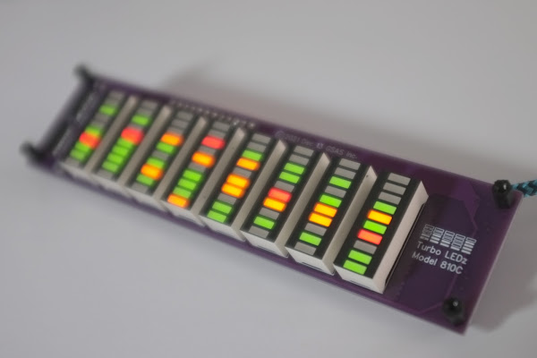
I am using the TLC5928 constant current sink driver to light up my LED bar graphs.

The neat thing about this part, is that you can set a current (for all 16 outputs) using a reference resistor. The higher the resistor, the less current the chip will output. So far so good.

If you have a LED bar graph that has both GRN and RED LEDs in it, you have a problem, though. The RED is a lot brighter, and does not need nearly as much current as the GRN one. I see typically a factor 4x more current for green. However, the reference resistor sets the current for ALL channels, whether they have a red or a green LED on it.

So, how to proceed? Well, I decided to do add pulse-width-modulation for the red LEDs. I will still drive all channels with the same constant current, but the red LEDs will have their anode voltage (3.3V) interrupted at a few hundred hertz, with a specify duty-cycle. Whereas the green leds will keep seeing their uninterrupted voltage.

A GPIO pin can never deliver the current required to switch a whole bunch of red LEDs. So we introduce a little switch, called a Bipolar Junction Transistor of the PNP form.

When adding a discrete transistor to do perform this PWM job, I also need to add resistors, which makes the design more cluttered. Fortunately, you can buy pre-biased transistors that already house those resistors along with the transistor. I have evaluated 3 such pre-biased transistors for this job.

DTB114EK (R1 and R2 are 10kΩ)

DTB123TK (R1 is 2.2kΩ)

DTB113ZC (R1 is 1kΩ and R2 is 10kΩ)

Note that in my case, I have 3.3V at the emitter (pin1) and not GND.

I've found that a high R1 resistor at the base of the transistor causes the EMITTER->COLLECTOR current to be too limited when the transistor is switched on. Even when I have a continuous '0' at the base, to switch it on, the current does not get high enough to drive many LEDs. Hence, between these three, the DTB113ZC with a 1kΩ resistor at the base does the best job for my application. I find that if I have a bunch of LEDs drawing 109mA in total, and switch that current with the transistor, 90mA makes it through with the DTB113ZC, 79mA makes it through with the DTB123TK and 47mA makes it though with the DTB114EK.