Shot with Ernst Leitz Epis 400mm f/4.

Shot with N.P.L. 20" Anastigmat lens.

The Ernst Leitz lens:

The N.P.L. lens:

Shot with Ernst Leitz Epis 400mm f/4.
Shot with N.P.L. 20" Anastigmat lens.
The Ernst Leitz lens:
The N.P.L. lens:
I have recently released an open source tool called sotrace. It maps out the .so dependencies for a binary or library, and presents them in a nice graph.
When I run it on my lean, mean, simple test program that runs a Vulkan Compute shader, I get this graph of dynamically linked libraries.

So tidy!
Because I also wanted run-time loaded dependencies, I added a mode where you can run sotool on a process-id instead. Running it on a process of the exact same binary, I gaze into the chasm of complexity with despair:

Sweet Mother of Isaac Newton! What is this abomination?
This runs a compute kernel on a GPU, with no graphics output at all. Why is X11 pulled in? And even some wayland stuff? Ugh. This is what I've come to see as hidden dependencies. My program depends on them, even though it does not link against them.
Meanwhile, when I use CUDA instead of Vulkan, I get serenity back. CUDA FTW!

And for completeness, when I run the OpenCL version of my compute kernel:

So, if you are a developer on Linux, give it a try and be amazed at what you dredge up. Let me know your findings!
"Yours Truly, Bram, fighting complexity wherever he finds it.
So, my Photon Mapping experiments led me from CUDA to OpenCL (for better compatibility) and now to Vulkan for even better compatiblity. OpenCL is just not cutting it anymore: abandoned by Apple, ignored by AMD. The latter I found out when I tried to use OpenCL on a mobile Ryzen iGPU under Linux: no go!
So Vulkan it is. I have always found Vulkan to be intimidating. It is just too much, before you will ever see a single triangle on your screen. I am hopeful that Vulkan Compute is less cumbersome, and it seems to be that way.
You still needs heaps and heaps of configuration and setup code, though. And I am slowly making my way through that. You can follow my progress at MinimalVulkanCompute github.
Some other sources for inspiration are Sascha Willems' example and Neil Henning's example
Vulkan uses SPIR-V modules to represent the compute kernels. So I need to port my OpenCL or CUDA code to this. I think I can just transpile my OpenCL code into SPIR-V using Google's clspv project.
After building clspv it appears that it ingests my OpenCL code pretty well, as it manages to create SPIR-V output. So far so good. I still need to execute it in my Vk code. I wonder how much performance is lost by the intermediate step, compared to a native OpenCL driver?
Next order of business is to figure out if I should create staging buffers. For an iGPU, all memory is the same. But for a dGPU, I have a lot of options for which type of memory to use. For instance, using my RX580 Radeon dGPU, I see:
$ ./minimal_vulkan_compute
Found 3 physical devices.
8086:4680 iGPU Intel(R) UHD Graphics 770 (ADL-S GT1)
1002:67df dGPU AMD Radeon RX 580 Series (RADV POLARIS10)
10005:0000 CPU llvmpipe (LLVM 15.0.7, 256 bits)
7 mem types. 2 mem heaps.
4096 MiB of local memory [ device-local ]
4096 MiB of local memory [ device-local ]
15908 MiB of non-local memory [ host-visible host-coherent ]
4096 MiB of local memory [ device-local host-visible host-coherent ]
4096 MiB of local memory [ device-local host-visible host-coherent ]
15908 MiB of non-local memory [ host-visible host-coherent host-cached ]
15908 MiB of non-local memory [ host-visible host-coherent host-cached ]
I have the vulkan port finally working as it should. Some things that tripped me up: A Vulkan kernel gets the work group size from the SPIRV. Whereas an OpenCL kernel can just set it in the clEnqueueNDRangeKernel() call, at client side. This makes the clspv route a little tricky: we need to spec the workgroup size in the CL kernel source, using __attribute__((reqd_work_group_size(x, y, z)))
The end result is that the CL -> clspv -> SPIRV -> Vulkan overhead takes quite a bit of performance away. The overhead is tolerable on nvidia RTX, but it is too much on Intel:
NVIDIA GeForce RTX 3060 Laptop GPU NVIDIA Corporation with [30 units]
  OPENCL:
    rayt:  2953 µs
    boun:  2989 µs
    binp:  1458 µs
  CLSPV+VULKAN:
    rayt:  3543 μs
    boun:  3586 μs
    binp:  1224 μs
Intel(R) UHD Graphics 770 (ADL-S GT1)
  OPENCL:
    rayt: 22017 µs
    boun: 20927 µs
    binp:  7310 µs
  CLSPV+VULKAN:
    rayt: 44635 μs
    boun: 40133 μs
    binp:  8490 μs
Depending on the platform, my compute time goes up between +20% and +100% when using transpiled OpenCL kernels via clspv. I should also mention that I have found the performance difference between CUDA and OpenCL insignificant.
We have fallen for the folly of maximum GPU performance. It is the age of 450 Watt GPUs. Why is that?
There is absolutely no need to have 450 Watt GPUs. The sole reason they use that much, is for a few additional FPS in the benchmarks. For real-world use, that 450 Watt is useless, as I have come to conclude after running an experiment.
Traditionally, I have always used NVIDIA GPUs in my Linux boxes, for stability and performance. But today, I am running an (elderly) AMD RX580 in my main rig. NVIDIA on Linux does not give you much control over clock speeds and voltages, but CoreCtrl let's me adjust the clocks for the RX580.
I already knew that for the last few percent of performance, you need a heap more wattage. This is because Wattage increases linearly with clock speed, but quadratically to the Voltage. Increasing Voltage comes at a huge cost. Let's quantify that cost.
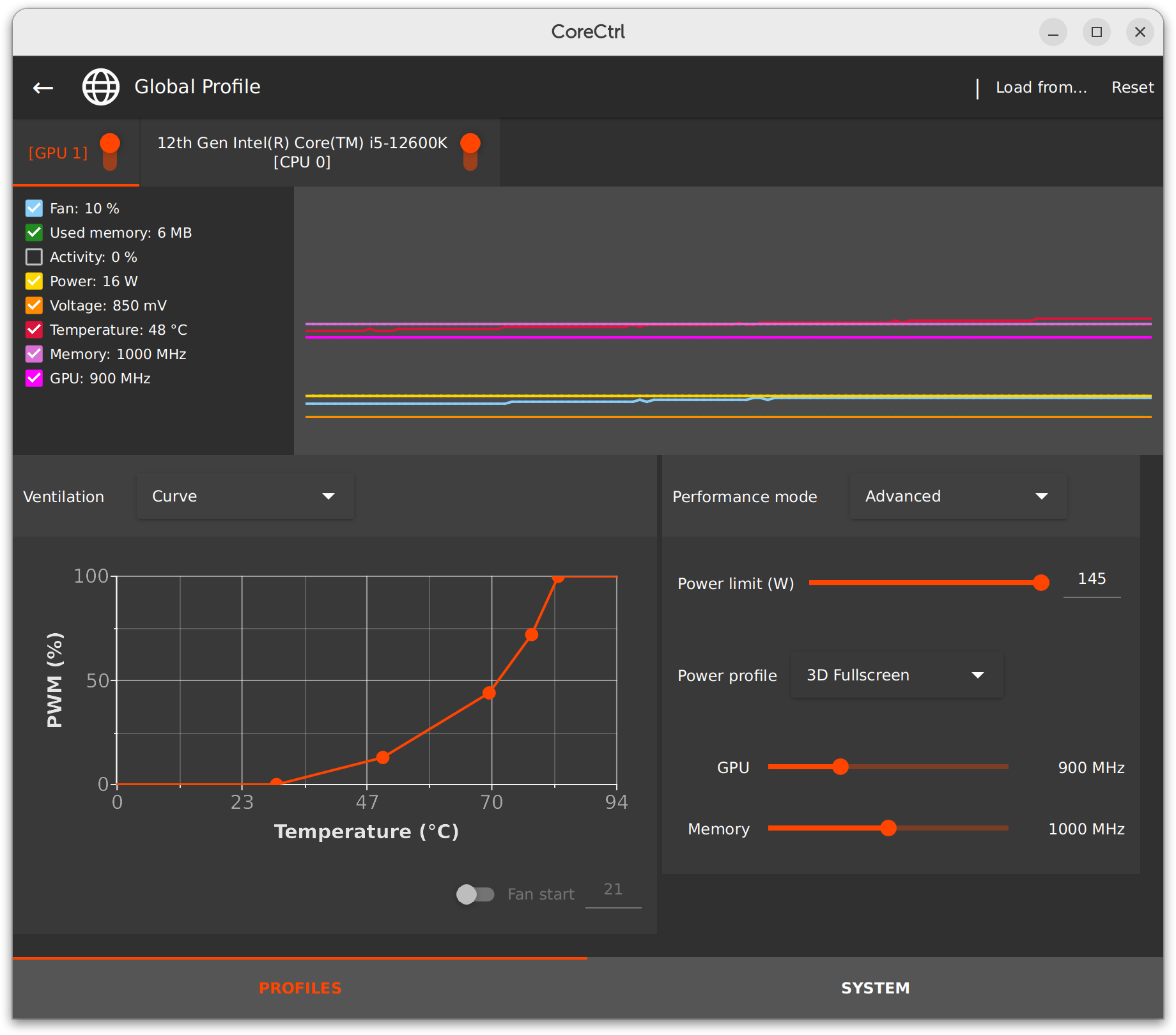
I benchmarked my Photon Mapping engine on two settings: 900Mhz GPU, 1000 MHz VRAM versus: 1360MHz GPU, 1750 MHz VRAM.
I then checked the FPS and the (reported!) Wattage. I guess for a more complete tests, measuring power consumption at the wall socket would have been better. Maybe another time.
So, with the higher clocks, we expect better performance of course. Did we get better performance?
     Clocks    FPS     Volt   Watt
   900/1000     38    0.850     47
  1360/1750     46    1.150    115
The result was even more extreme than I expected: For 145% more power consumption, I got to enjoy 21% more frames/s.
Not only that. The high-clock setting came with a deafening fan noise, whereas I did not hear a thing at low Voltage.
Which now makes me ask the question: Shouldn't those benchmarking youtube channels do their tests differently? Why are we not measuring --deep breath-- frames per second per (joule per second) instead? (As Watt is defined as Joule/Second.)
We can of course simplify those units as frames per joule, as the time units cancel each other out.
Hot take: LTT, JayzTwoCents, GamersNexus should all be benchmarking GPUs at at lower Voltage/Clock setting. I do not care if RTX inches out a Radeon by 4% more FPS at 450Watt. I want to know how they perform with a silent fan, and lowered voltage. Consumer Report tests a car at highway speeds, not on a race track with Nitrogen Oxide and a bolted on Supercharger. We should test GPUs more reasonably.
Can we please have test reports with Frames per Joule? Where is my FPJ at?

UPDATE: I can't believe I missed the stage-4 galaxy brain. We can invert that unit to Joules/Frame instead!


Because I am a sucker for Linux SBCs, I got myself a Sipeed Lichee Pi 4A RISCV SBC. And remarkably, it can do OpenCL too! Which means I can try my Photon-Mapping CL kernel on it.
Even though it can run OpenCL kernels, I did find that the OpenCL implementation is not the most stable one: As soon as I try to fill a buffer with clEnqueueFillBuffer() it will crash.
The performance of my kernel on this SBC was incredibly bad though: three orders of a magnitude slower than a desktop GPU. Which made me wonder what the performance would be on my Raspberry Pi 400.
Eben Upton designed the VideoCore IV GPU in the original rPi. So surely, the software support should be excellent. Sadly, there is no OpenCL for the rPi4.
CLVK to the rescue! This sofware will translate OpenCL kernels to Vulkan compute kernels. Even though RaspberryPi OS would not work with it, Ubuntu 23.04 for rPi would, as it had a newer Mesa.
Which brings us to the next disappointment: even though there is a Vulkan driver for the rPi4, this driver lacks important Vulkan extensions. It cannot handle 16-bit floats, nor can it handle 8-bit ints.
unknown NIR ALU inst: vec1 16 div ssa_217 = b2f16! ssa_182
This leaves us with a rather lacking implementation. Since I wrote my Photon Mapper for FP16, this experiment has to be shelved.

Once again, I find myself porting CUDA code to OpenCL. And I had to remind myself of the process, and the differences between the two. Let's document, so future Bram will catch up quickly again.
The major difference is of course compatibility. OpenCL is supported by Nvidia, Amd, Intel, etc. CUDA is only supported by Nvidia. It's the whole reason of this porting exercise.
The CUDA-kernel can be pre-compiled by the developer using nvcc, and then be shipped as a PTX file. The OpenCL-kernel typically ships as C-like source.
The function definition of a CUDA-kernel gets prefixed with __kernel whereas an OpenCL uses a __global__ prefix.
A CUDA-kernel uses blockIdx and blockDim to determine which sub-part of the input data it is supposed to process. An OpenCL kernel uses get_global_id() instead.
Using 16 bit floating point arithmetic is as easy as #include <cuda_fp16.h> and using __half. On OpenCL you need to check for an extension and add #pragma OPENCL EXTENSION cl_khr_fp16 : enable
In CUDA, constant input data is prefixed with __constant__ which the host then sets with the cuMemcpyHtoDAsync() function after getting the symbol using the cuModuleGetGlobal() function. In OpenCL if the constant input data is large, you prefix it with __global__ and the host sets it with the clCreateBuffer() and clEnqueueWriteBuffer()functions.
Half float literals need a constructor in CUDA: __half(1.0) but can use a suffix in OpenCL, where 1.0h can be used.
Many operators need a function call in CUDA. The reciprocal in CUDA is hrcp(x) and a simple <= on a half float becomes __hlt(a,b) which makes it less legible.
A minor diffence is that CUDA's atomicAdd is atomic_add in OpenCL.
CUDA has asserts but OpenCL does not.

When it comes to video games, I don't think Minecraft has been surpassed. Like all the best games, it has a simple premise: mine blocks in an infinite world, and use them to craft other blocks. But from this simple fundement, a master piece arose.
Even after the purchase by Microsoft, the game is still available for Linux, as Mojang maintains a Java version of their game. Lately, I have been looking into running a server, and intend to write custom code, server-side, to see what can be done with that. Minecraft lets you modify the client code. But this post investigates the modification of the Minecraft server.
Minecraft modding has a long history. But it appears that my best entry point would be SpigotMC.
After executing BuildTools.jar, I ended up with a file called spigot-1.19.3.jar which I copied to my minecraft server root directory. Instead of running minecraft_server.1.19.3.jar I now run the spigot jar file instead.
To make sure newer minecraft clients can connect, you can put ViaVersion.jar in the plugins directory.
Next up, is finding out how to write custom server code. So far I have found Kody Simpson's Youtube series an excellent resource.
Bukkit is a Java Interface, and it is implemented by CraftBukkit.
CraftBukkit is implemented using net.minecraft.server code.
This means that the same object can be referenced and used at three different levels. For instance, the player exists as Bukkit's Player, as CraftBukkit's CraftPlayer and as Mojang's EntityPlayer.
Only the Bukkit interface remains stable between releases, and can be used on different minecraft server versions. Also, the NMS (net.minecraft.server from Mojang) code is decompiled, and obfuscated.
Does coding an NPC require NMS? Or can it be done in SpigotMC? If not, what about PaperMC?
To deal with the obfuscation of n.m.s. there are the so called Mojang mappings. Initially I was unable to use those with Java 19. But using a development version of SpecialSource I was able to use n.m.s. with Java 19.
When getting confused in API terminology, this is a good reminder.
I noticed that using the remapped API, really slowed down my iteration speed. Building my plugin went from a few seconds, to 1 minute, because the remapper is slow.
The first restults from my experiments: The Little Vex That Could. A construction-buddy that builds castles from IKEA flat-packs.

So far, I have been programming my µcontrollers using the Arduino IDE. As I progressed with my TurboLEDz experiments, I came across different µcontrollers, including the ESP32 series from Espressif.
Espressif actually has their own SDK, which targets the command line. As I feel quite at home on the command-line, I decided to switch over to the Espressif SDK, which is called ESP IDF, or ESP IoT Development Framework.
This environment is based on cmake and python tools that wrap it. Nowadays, it recommends to use it with vscode IDE, but frankly, I found it to work better without.
You mainly interface with the build environment using the idf.py tool. The typical sequence would be:
    $ idf.py set-target esp32s2
    $ idf.py build
    $ idf.py flash
    $ idf.py monitor
And what I really appreciate from ESP IDF is that you can code in pure C, without any C++ stuff involved. No need for .ino files, either. Plain, simple C. I love it.
Speaking of Internet of Things... I've always found it to be a nebulous term. But I guess it pertains to devices that don't have a screen, keyboard, mouse, but do have Ethernet/WiFi? And thanks to the march of progress, those tiny little devices are typically as capable as desktop computers were two decades ago?
My favourite µcontrollers are RISCV based. And some devices really blur the line between µcontroller and single-board-computer. Like the Pine64's Ox64 which is powerful enough to run Linux (but witout the protected memory, I think.)
I also like the ESP32 with two cores, a lot. It enabled me to create this voice-changer where the two cores can tag-team: one core is computing the Fourier Transformations while the other is doing I2S, and then they switch. So one core does everything for the odd-numbered batches with samples, and one core does everything for the even-numbered batches. Nice low-latency concurrency. Yay! But that project was all in Arduino IDE.
For my fist IDF project, I wrote a single-header-file piece of code for use with Adafruit's LED backpack. See my ledbp.h gist. It sits on top of Espressif's driver/i2c.h code.
Caveat Emptor! At the time of writing, ethernet, wifi and SD-Card are not working. It's good to realize this before jumping into this.
Things have improved a little, since writing PART 1 of my experience. Instead of a patched bflb-mcu-tool to flash, it is now possible to use a modified picoprobe [DOWNLOAD HERE] with the Dev Cube flashing tool.
Also, there is a patch for the PIN definitions so that we can capture the UART of the D1 core (which is a T-HEAD C906) on pins GPIO17/GPIO16.
With the fixed pin definitions we can hook up a USB to UART dongle, like the CH340G, to the second UART as shown below.
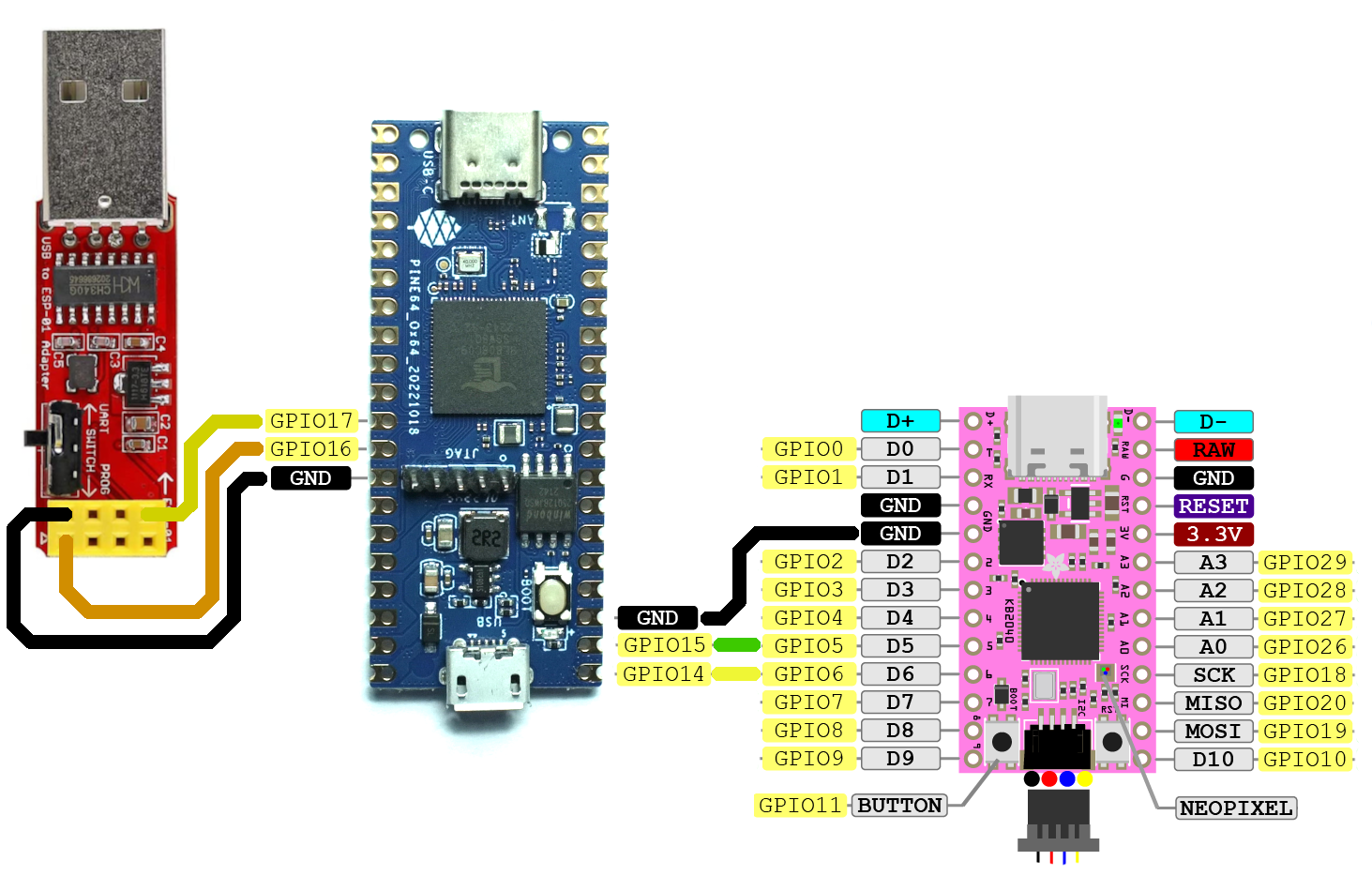
In this picture, the red dongle is to capture the output from the linux console running on the T-HEAD C906 core. The pink dongle is to program the Ox64. Both of these need to be connected to your PC. The Ox64 itself needs no connection to the PC, other than a power feed into the Micro-USB.
So, once we wired this all up, flashed to binaries, what do we get?
We get root!
And that's after booting in a blistering 0.22 seconds!

I love Linux on a diet. So mean and lean.
Next up: Can we get networking?
Yes, you read that right... for $8 you can run linux on a RISC-V computer. And not just a stripped down kernel without an MMU. No, the Ox64 comes with capable RISC-V cores. Heck, and not just one core, but three cores (all different.) Exciting times!
Caveat Emptor! At the time of writing, ethernet, wifi and SD-Card are not working. It's good to realize this before jumping into this.

It looks like a microcontroller, but behaves like a UNIX machine. Sweet, or what? Getting it up and running, though, is far from trivial. There are so many hurdles to take!
Hurdle 1: You cannot program it using USB, like you would an Arduino, ESP32, Stamp-C3 or rPi Pico. Nope... this needs to be programmed via the UART TX/RX pins. In the picture above, you can see them hooked up to GPIO14 / GPIO15 and GND.
Hudle 2: The flashing tool Dev Cube will crash on launch when using Ubuntu on Wayland: you have to switch to Xorg instead.
$ ./BLDevCube-ubuntu
Warning: Ignoring XDG_SESSION_TYPE=wayland on Gnome. Use QT_QPA_PLATFORM=wayland to run on Wayland anyway.
/usr/lib/x86_64-linux-gnu/gio/modules/libdconfsettings.so: undefined symbol: g_log_structured_standard
Failed to load module: /usr/lib/x86_64-linux-gnu/gio/modules/libdconfsettings.so
GLib-GIO-Message: Using the 'memory' GSettings backend.  Your settings will not be saved or shared with other applications.

(BLDevCube-ubuntu:54646): GLib-GIO-ERROR **: Settings schema 'org.gnome.settings-daemon.plugins.xsettings' does not contain a key named 'antialiasing'
Trace/breakpoint trap (core dumped)
So, UART programming then... fine, we'll just use one of those little CH340G dongles. I got one off Amazon, but it would not work... every time the handshake would fail in Dev Cube (hurdle 3).
Luckily, some people found out that you can program it with an RP2040 device, like the rPi Pico. I had a KB2040 from Adafruit lying around, so used that.

Which puts us at hurdle 4: How to turn a KB2040 into a serial bridge between PC and Ox64? Hook up GPIO-4 of the RP2040 to GPIO-15 of the Ox64. Hook up GPIO-5 of the RP2040 to GPIO-14 of the Ox64. Also, connect the grounds, of course. See below how to hook up for flashing the M0.\

Then we need to load our RP2040 with picoprobe which we can do by holding BOOT while powering up, and feeding it the uf2 file with picoprobe.
Ok, so now we can flash it then? Unfortunately, no, hurdle 5: DevCube is still not able to flash the Ox64, but we can use bflb-mcu-tool instead.
Ok, but with bflb-mcu-tool, we are all set! Are we? Introducing hurdle 6: we need to modify the tool before it will work for us. This means stripping DTR and RTS stuff from the tool by editing the ~/.local/lib/python3.10/site-packages/bflb_mcu_tool/libs/bflb_interface_uart.py file. Here is my copy.
So with the Ox64 powered via MicroUSB, and the RP2040 connected to my PC using USB-C, I can finally flash something.
For that, I took the low_load_bl808_m0.bin from the bl808 linux guide and flashed it with:
$ bflb-mcu-tool --chipname=bl808 --port=/dev/ttyACM2 --baudrate=2000000 --firmware=out/low_load_bl808_m0.bin
After which I now get output from my Ox64, via my KB2040 to my PC:
dynamic memory init success,heap size = 156 Kbyte
E907 start...
mtimer clk:1000000
psram clk init ok!
Ok, a modest start, but the Ox64 is talking to my PC now! Yay! Come back to my blog at a later time to see if I will manage to run Linux on the Ox64! Because as I understand it, I also need to flash something to the D0 and then flash the actual OS as well.
UPDATE: Here is PART 2.

I've released the 6th product under the TurboLEDz name. This time it is a voice changer. It makes you sound like a bad asss, by doing real time FFT, frequency manupulation and iFFT to go back to the time domain. It's built with an I2S mic and I2S DAC/Amplifier. To make the μcontroller capable of keeping up with the samples, I've programmed it as multi-threaded, dual core. So if one core is busy doing math, the other is still available to do IO. And the cores will tag-team. One core for the even numbered chunks, the other core for the odd numbered chunks. It works really well, as you can see in the video.
I bought three super capacitors from Adafruit, model DDLE2R5LGN701KAA5S. They are rated at 700 Farad at 2.5V. (They have very little stock left, at time of writing, so if you want them too, act quickly!)
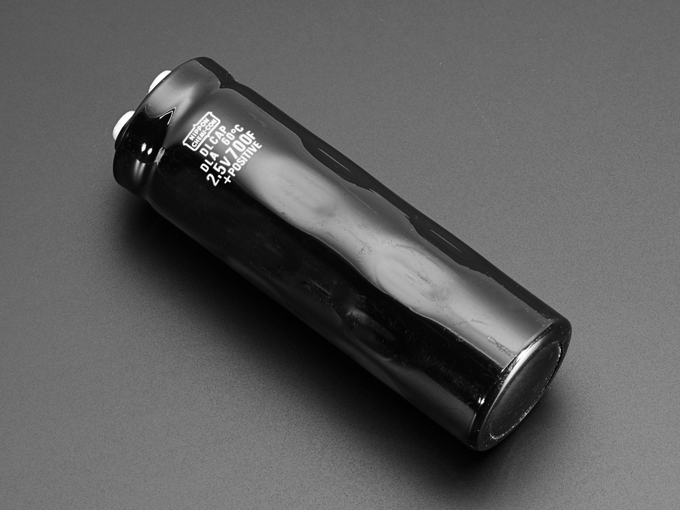
If I place them in series, I will end up with 233 Farad at the very maximum of 7.5V. However, charging to the max 7.5V is dangerous: one of the capacitors can easily overcharge and explode, that way. Unless you balance the capacitors.
Balancing a capacitor bank is not trivial. But there seems to be an alternative, as offered by Patrick of EngineeringShock.
Patrick's advice is to charge the capacitors to 80% of their nominal Voltage, so that even if there is a mismatch in internal resistance between the capacitors in series, none of them will overcharge. I like this approach, as it is simpler, does not require extra circuitry, at the cost of lost capacitance.
So if we charge a 7.5V bank to 80%, we get a charging voltage of 6 Volts. Let's make that our target. When we have have our bank charged to 6V, we can feed that into a voltage regulator, and as the bank drains to 3.3V, we should be able to ride from 6V to 3.3V and run a μcontroller off that, or some other low-power electronics.
And this leads me to my next objective: how to generate a steady 6V charging voltage? I would like to use solar panels for this. So let's dive into photovoltaics.
Reading the specification of a PV panel, there is the nominal voltage, which we can't really rely on. Then there is the Voc (Open Circuit Voltage) which we will measure if there is no current flowing. And also the Max Power Voltage, which is lower.
I need to read up on how to make sure that a photovoltaic panel output a steady 6V, and never any higher, at a tight tolerance. PV panels typically use charge controllers for that, but I want something simple. Maybe an opamp?
I am taking a different approach. I've decided to charge the capacitors in parallel, not in series, at a steady 2.5V.
To achieve this, I take input from a solar panel (with wildly varying voltage, and current) and convert that with a buck-converter to 2.5V that can be used to charge the capacitors.
I then use the capacitors as input for a boost-converter that brings a varying low voltage (It is only 2.5V when fully charged, and they discharge linearly) to a steady 3.3V. This I can then use in a client circuit, typically a μcontroller with some peripherals attached.
Just for the heck of it, I am test-driving a RISCV Linux SBC called the Sipeed Lychee RV 86.
When I plugged it in, nothing happened. No console ouput on the USB tty, nothing on the screen. It turns out there is no software loaded on it: the flash memory slot is empty. So you need to provide your own storage, and own OS.
First attempt is with a "debian-minimal" install.
# dd if=debian-minimal-licheerv.img of=/dev/sdb bs=32K
134272+0 records in
134272+0 records out
4399824896 bytes (4.4 GB, 4.1 GiB) copied, 248.155 s, 17.7 MB/s
Those were the write speeds to my "Sandisk Extreme PLUS." Hmm... that does not seem to be an extreme speed, to me. It has a U3 designation. Oh well. UPDATE: Lexar x1000 was even worse: 15.7 MB/s and the write speed slows down, as you write more. Remind me never to buy Lexar SD cards again.
And it works! With the card inserted, I now get a login prompt on ttyUSB0 in 32 seconds. Not bad at all.

Somehow, it takes a long time for the Ethernet device to show up with ifconfig command? When it does, ifup usb0 is not working: ifup: unknown interface usb0
When I make usb0 interface known, the dhcp client will receive no offers, unfortunately. Despite the Ethernet light blinking, so there is network activity.
I have been able to work around the need for a proprietary MSWindows tool to use the Lichee RV disk images. With the OpenixCard tool, you can extract a normal image, that you can write with dd to an SDCARD.
$ file ~/Downloads/LicheeRV_Debian_86_480p.img
/home/bram/Downloads/LicheeRV_Debian_86_480p.img: data
./OpenixCard -i ~/Downloads/LicheeRV_Debian_86_480p.img -d
...
$ file /home/bram/Downloads/LicheeRV_Debian_86_480p.img.dump.out/LicheeRV_Debian_86_480p.img
/home/bram/Downloads/LicheeRV_Debian_86_480p.img.dump.out/LicheeRV_Debian_86_480p.img: DOS/MBR boot sector; partition 1 : ID=0xc, start-CHS (0x2,35,2), end-CHS (0x2,163,1), startsector 34336, 8064 sectors; partition 2 : ID=0xee, start-CHS (0x0,0,2), end-CHS (0x0,33,1), startsector 1, 2079 sectors
$ sudo dd if=/home/bram/Downloads/LicheeRV_Debian_86_480p.img.dump.out/LicheeRV_Debian_86_480p.img of=/dev/sdb bs=1M
8237+1 records in
8237+1 records out
8637726720 bytes (8.6 GB, 8.0 GiB) copied, 435.776 s, 19.8 MB/s
The Debian image works great. I removed all X11 stuff, and will just use fb0.
I noticed that eth0 mac address is randomized at each boot, so I had to create an entry in /etc/network/if-pre-up file:
#!/bin/sh

IFCONFIG=/sbin/ifconfig

if [ ! -x $IFCONFIG ]; then
        exit 0
fi

if [ "$IFACE" = eth0 ]; then
        $IFCONFIG $IFACE hw ether XX:XX:XX:XX:XX:XX
fi
To set the timezone: $ timedatectl set-timezone America/Vancouver
If not using wifi, it is probably a good idea to remove xr829 from /etc/modules file.
I have been removing a lot of packages, trying to get a minimal install. To aide this effort, I decided to graph the dependencies, to see which cuts I can make in the dependency chains.

The D1 CPU is RV64IMAFDCVU which means it does: INTEGER MUL/DIV, Atomic, SP FP, DP FP, Compressed Instructions, Vector Operations, User.
Sadly, it has no conditional move operations.
Tyring to build a new kernel for this, using these instructions. Oof! getting the linux kernel source with git history... 5.2GByte. These sizes of these things are getting out of hand.
TurboLEDz has released another product: the Desk-side Stock Ticker. It connects to WiFi with WPS, and automatically retrieves stock quotes from the Internet.
— TurboLEDz (@TurboLEDz) April 12, 2022
A CPU does not wear down with use like a car engine does. Hence, a car has an Odometer, and a CPU does not. I does not need one.
But, just because it doesn't need one, does not mean it cannot have one! I decided to make one. World.... please meet the TurboLEDz CPU Odometer.
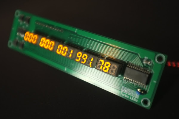
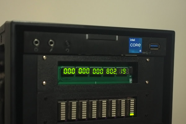
It uses the turboledz daemon for Linux to keep track of the jiffies (centiseconds) that were spent computing, aggregated over all cores. If your computer is idling, it ticks very slowly. If your computer is pinning all cores at 100% it ticks up very fast. The odometer value is stored in between reboots on your system.
I am selling it on my tindie store.
I'm doing my first exploration of BSD. After some struggles with the OpenBSD installer, I installed FreeBSD instead. Here as some findings.
You can install software from source in /usr/ports and to do that, you need the portsnap command to fetch the tree.
My 1280x768 monitor is used as a 640x480 console. I tried the following in /boot/loader.conf which did not work:
kern.vt.fb.default_mode="1280x768"
efi_max_resolution="1280x768"
I tried to use hidraw using this in loader.conf which also did not work for me:
hidraw_load="YES"
hw.hid.hidraw.debug="9"
hw.hid.hidbus.debug="99"
hw.usb.uhid.debug="99"
My 12th gen Intel machine cannot boot version 13 of BSD. Instead I need to use 14-CURRENT.
I could only get the installer for 14-CURRENT to run by installing a discrete Radeon GPU, which then let me set the BIOS option CSM enabled.
Game Studio Abraham Stolk Incorporated, has done a pivot. No games, for now, instead: consumer electronics.
Yep, I have refashioned myself as a electronics designer. And my new brand is TurboLEDz.
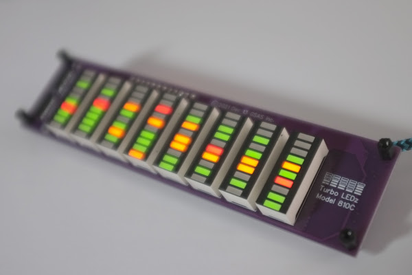
These devices will plug in your motherboard USB, and are to be mounted in your PC case. They will then display either the CPU load (Model88s) or the CPU Core Frequencies (Model810c) as a running graph.
You can buy them on my Tindie Store.

Complex software will be guaranteed to have bugs in it. And most of the bugs are caused by state changes.
The human mind has limited capacity of keeping track of state (data, variables.) Hence, there is a discrepancy between what the state looks like in the programmer's mind, and what it actually looks like.
How does state change?
Where in the code does the state change?
When does the state change?
In what order does the state change?
And even... why doest the state change?
The mental picture of those, formed by the programmer, is very poor.
So.. bugs!
There is of course a paradigm where state-change plays a zero roll: functional programming. But despite decades of trying, we have not been able to practically use that in complex software. Mainly because the real world deals with state. Try making a video game that carries no state!
John Carmack once did an impromptu talk on functional programming and video games, and made in interesting observation that you could write an AI/sim that takes the entire world as function input, and produces the entire world as its output.
About John's example of a one-person hallway... I think the solution is simple. Input for hall-entering needs more than the current entity. It needs a list of all other entities that want to enter. Then use a heuristic to choose which one can actually enter. Done.
So yeah... complex state changes. As long as we have not harnessed the complexity of state, I find it pretty futile to crusade against C's unsafe memory referencing, e.g. A bug caused by following a dangling pointer is so shallow, compared to a bug caused by asynchronous state changes racing to completion. Throw in multiple threads, multi-player, and it will be too hard to reason about.

I've been learning a lot about transistors, lately. This is because I found myself having to switch a load that would be too large for an IO pin. Here I summerize my newly gathered knowledge on them.
A BJT transistor is switched ON/OFF using current at the base. This current is then multiplied at Collector/Emitter.
To tune the current flowing through the base, we need a bias resistor. This makes PCB design bulkier, but you can get pre-biased transistors. I find I need to get them with a low Ohm bias, else my transistor will not switch fully on.
BJT comes in two variants, NPN and PNP. The schematic symbol differs in which way the arrow points. Mnemonic: NPN has the arrow "Not Pointing iN."
PNP transistors can be used to switch a load at its high-side: You cut the load's connection to V+ ON/OFF.
NPN transistors can be used to switch a load at its low-side: You cut the load's connection to GND ON/OFF.
MOSFET transistors are often a better choice, unlike of BJT's current based switching, the switch based on voltage at the gate.
MOSFET comes in two variants, P-CHANNEL and N-CHANNEL.
P-CHANNEL transistors can be used to switch a load at its high-side: You cut the load's connection to V+ ON/OFF. A 0V at the gate will switch on the transistor. Source is connected to V+ and Drain is connected to the load.
N-CHANNEL transistors can be used to switch a load at its low-side: You cut the load's connection to GND ON/OFF. A V+ at the gate will switch on the transistor. Source is connected to GROUND and Drain is connected to the load.
To simplify a PCB design, you can get two transistors that share its housing in an "Array."
I am evaluating bi-colour LEDs that are RED/GRN, and can be mixed to ORANGE/YELLOW. The two candidates are SunLED GMDKVGX10D and KingBright DC10EGWA.
I've found that the SunLED has a bright GREEN with an even brighter RED. You need to drive the green channel with at least double the current of the red, to match them. I find that 1kΩ and 2kΩ work for my application.
The KingBright, on the other hand, doesn't show much difference between the RED and GRN brightness. But both are far less bright than the SunLED. Even though the KingBright has the term "High Efficiency" in the data sheet? When I limit both RED and GRN with 470Ω I find it is still quite a bit dimmer than the SunLED at 1kΩ/2kΩ.
What both models do the same: they have the GRN/RED LEDs share their cathode, not their anode. A common-anode design would have been so much more convenient. You would have been able to drive it with a constant current LED driver that is a current sink. All constant current LED drivers that I could find are current sinks, so none of them can be used with these LEDs. So not Texas Instruments TLC591x, nor TLC592x and neither a Maxim6966 would work. I consider this a strange design decision.
Another feature I miss, is an 8-segment version of these bar-graphs. It's just more convenient to work with 8-bit quantities. Or in the case of bi-colour bar-graphs: 16-bit would be preferable over 10-segment 20-bit units. Monochromatic, and fixed-colour bar-graphs come in more varied sizes, like 8-segment, 10-segment and even 12-segments sometimes.
